Project 01 · Research · Controls
Real-Time Control of a Pneumatic Actuator
I built and hardware-tested a cascaded controller for a double-acting pneumatic actuator. The outer loop converted position error into chamber-pressure targets, and the inner nonlinear model predictive control (NMPC) loop chose pulse-width-modulated valve commands. In selected hardware run 109, the system followed a multi-position sequence with 2.62 mm root-mean-square error while the controller averaged 0.17 ms per sample.
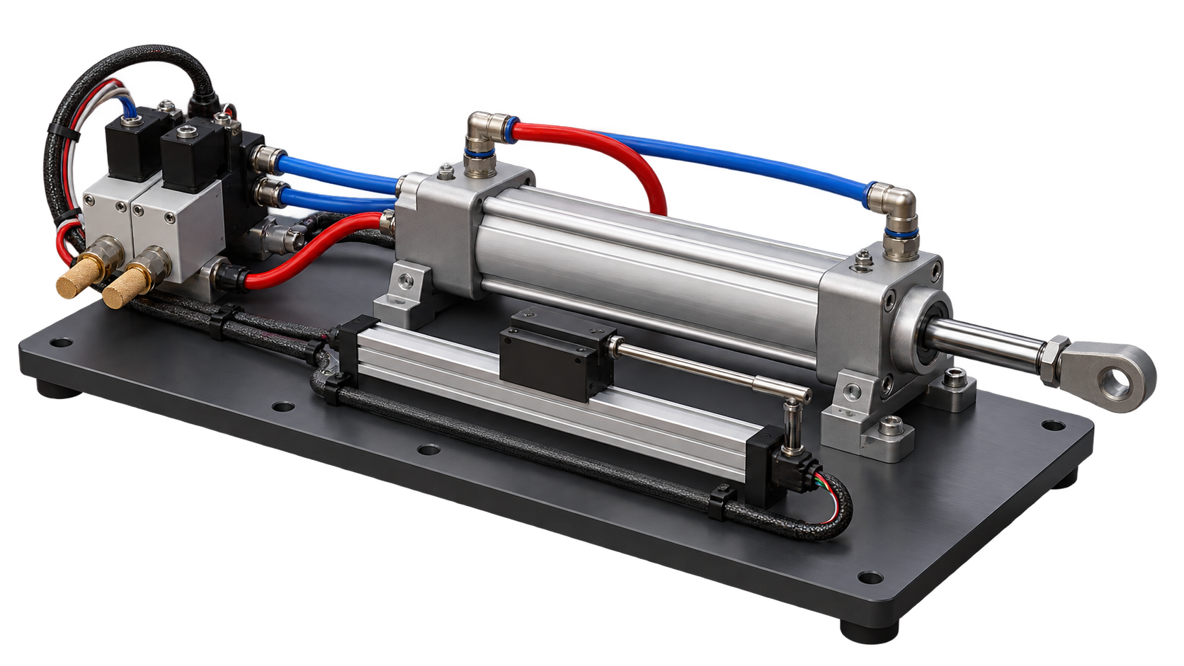
Source & evidenceI keep the lab source and controller-specific files private.
- Role
- Robotic System Engineering Researcher
- Laboratory
- Robotics & Manufacturing Automation Lab · McMaster
- Tracking
- 2.62 mm root-mean-square error · 1.55 mm mean absolute error
- Controller compute
- 0.17 ms mean per sample
At a glance
The system, my controller work, and the validation results.
The problem
I needed to control a lightweight, compliant pneumatic actuator despite compressed-air dynamics, valve deadzones, coupled chamber pressures, changing supply conditions, and strict real-time constraints.
My contribution
Starting from an existing apparatus and baseline controller, I modified the valve-control software to drive the valves with pulse-width modulation (PWM). I then designed calibration and system-identification experiments, implemented the cascaded motion/pressure controller, integrated sensor acquisition and position/pressure safety monitoring, and planned and analyzed hardware trials.
Selected hardware trial
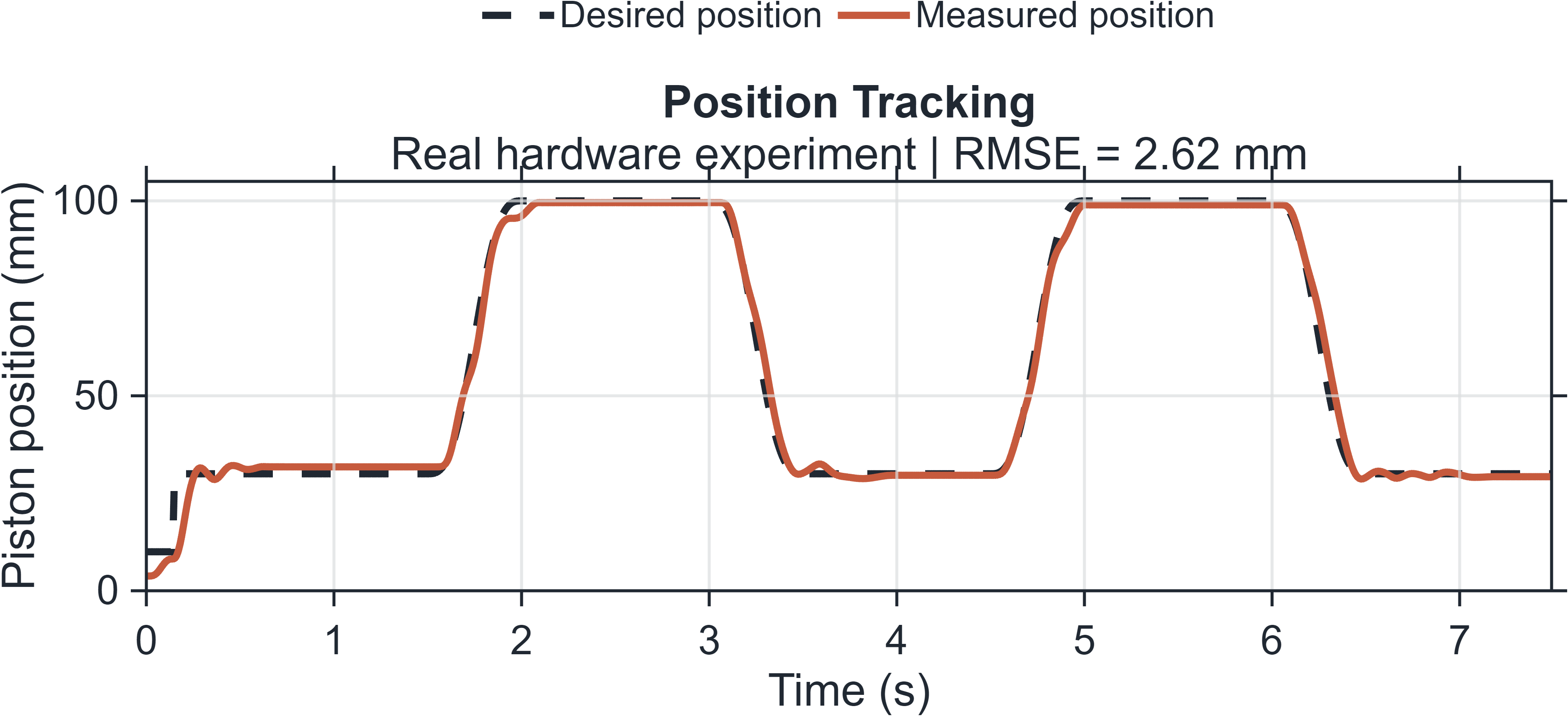
In selected hardware run 109, my controller followed a 7.49 s multi-position sequence with a 2.62 mm root-mean-square error (RMSE) and 1.55 mm mean absolute error (MAE). It averaged 0.17 ms of computation per sample and triggered no safety shutdown. I estimated 7.48 J of valve electrical energy for that trial, but I do not claim energy savings or repeatability because I do not have a matched baseline or repeated-run study.
01 / System boundary
Characterize the system before closing the loop
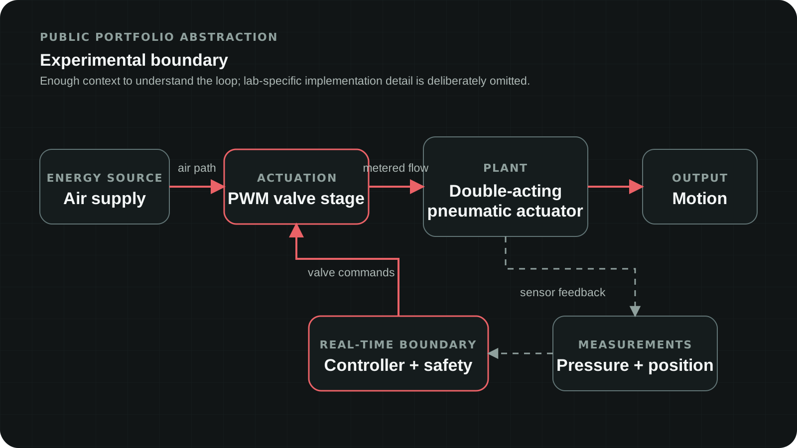
The experimental loop combined an air supply, PWM valves, a double-acting actuator, pressure and position sensing, and a real-time controller. I designed calibration and system-identification experiments to characterize valve response, chamber pressure, and piston motion, then used hardware data to iterate the models and controller before closed-loop trials.
02 / Control architecture
Turn the controller into real-time code
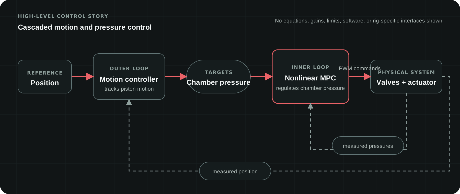
The architecture I implemented was cascaded: an outer motion loop converted position error into chamber-pressure targets, and an inner nonlinear model-predictive pressure loop used measured pressures to select PWM valve commands. Position, pressure, and safety feedback closed the real-time hardware loop.
03 / Validation
Example hardware run
This short clip shows the pneumatic actuator moving through a programmed position sequence.
04 / Results
Results and validation
The position-tracking graph shows desired and measured position over time. Mean absolute error was 1.00 mm at 30 mm and 0.81 mm at 100 mm. The largest error occurred around startup and rapid transitions, identifying transition response as the clearest next improvement target.
05 / Poster
Research poster
The poster brings the experimental system, control architecture, and selected hardware result together in one view.
Open research poster (PDF)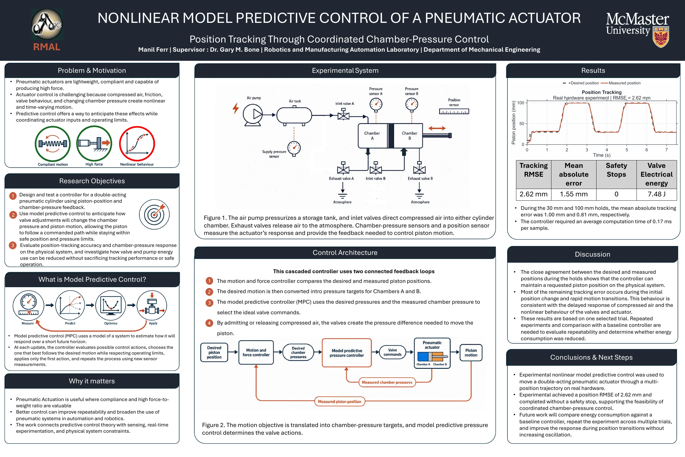
Tools & technologies
- Nonlinear MPC
- Cascaded control
- Real-time control
- System identification
- PWM actuation
- Data acquisition
- Hardware validation
- Safety monitoring