Project 02 · Embedded flight control
Custom ESP32 Quadcopter
This was a solo project covering the aircraft, handheld transmitter, firmware, and supporting application. I built the complete stack without using a black-box flight controller and reached a short untethered indoor lift, though residual yaw prevented a stable hover.
View Drone code on GitHub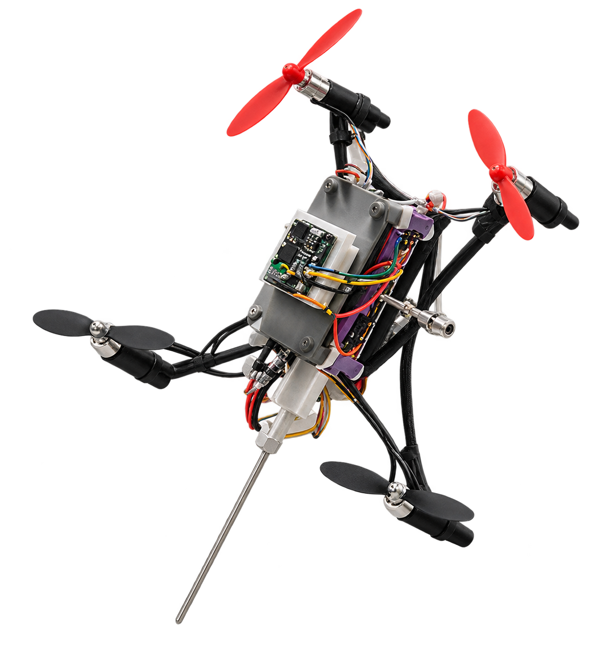
At a glance
How I built it, debugged it, and got it off the ground.
The problem
I set out to build and flight-test a brushed quadcopter around an ESP32 and a GY-87 inertial measurement unit (IMU), while keeping every layer—from mechanics and electronics to estimation and control—understandable end to end.
My contribution
I independently designed and printed the aircraft, assembled and rebuilt its electronics, built the handheld transmitter, and developed the firmware and supporting application. I adapted a dRehmFlight-derived estimator and control structure to an ESP32 receiver and ESP-NOW transmitter, then implemented the aircraft-specific radio link, status reporting, calibration, motor-output mixing, test modes, and failsafe behavior.
Documented result · project footage
I recorded a short untethered indoor lift, but not a stable hover. The project montage shows a brief airborne attempt after I corrected the control-axis signs and tuned the roll and pitch loops. Residual yaw remained. Because I did not repeat the test or isolate its cause, I do not claim repeatable flight or attribute the yaw to one confirmed fault.
01 / System
Integrate the airframe, electronics, radio, and flight stack
I modelled the frame in Autodesk Inventor and printed it on a Prusa MK4S around an ESP32 DevKit V1, the MPU6050 accelerometer and gyroscope on a GY-87 module, two TB6612FNG drivers, four 8520 brushed motors, a one-cell battery, and a 5 V boost supply. A second ESP32 and two joysticks formed the handheld transmitter.
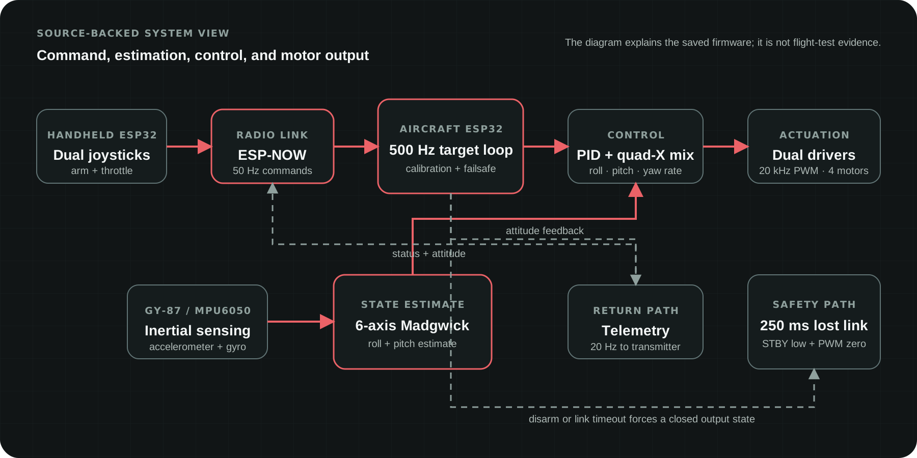
I configured the receiver for a 500 Hz target loop with six-axis Madgwick estimation, roll/pitch angle PID, yaw-rate PID, quad-X mixing, and 20 kHz PWM. I used ESP-NOW for 50 Hz commands and 20 Hz telemetry; startup, disarming, and a 250 ms lost-link timeout all set the motor outputs to zero.
02 / Electrical design
Document the receiver, transmitter, and power path
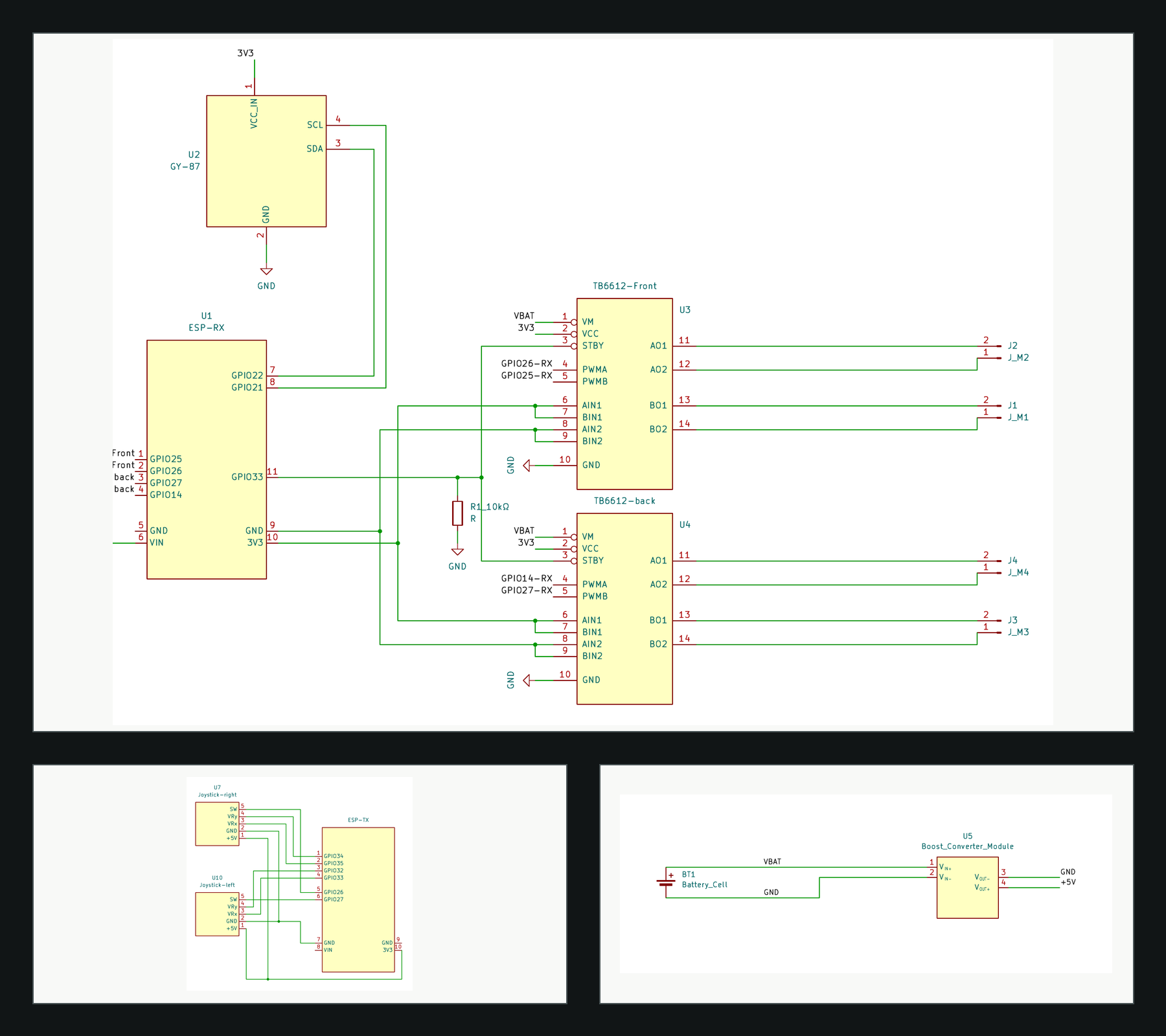
I captured the intended wiring in a three-sheet KiCad schematic. The receiver sheet connects the GY-87 to the ESP32 over I2C, routes four PWM channels through two TB6612FNG drivers, and uses a 10 kΩ pull-down on driver standby. The controller sheet maps two joystick modules to the transmitter ESP32, while the power sheet separates the battery rail from the boosted 5 V rail.
The export records design intent and pin mapping. It is not an as-built continuity check or proof that every prototype connection matched the drawing, so the hardware photographs and test clips remain separate evidence.
03 / Debugging
Debug one subsystem at a time
A reversed battery connection destroyed the first ESP32, so I desoldered the electronics and rebuilt the aircraft around a replacement controller. I then used one-variable tests: swapping motors localized a dead output to a driver, loading the earlier equal-duty build separated the motor path from the IMU-dependent firmware path, checking the I2C wiring exposed a bad solder joint, and reviewing sign conventions exposed pitch and yaw errors.
Before PID tuning, I repositioned the IMU and battery, changed the propeller geometry after observing cleaner raw sensor data, and added a calibration routine that runs after the disarmed aircraft is held still and level for three seconds. I then ran tethered tests before the recorded short untethered lift.
04 / Flight test
From tethered tests to a short untethered lift
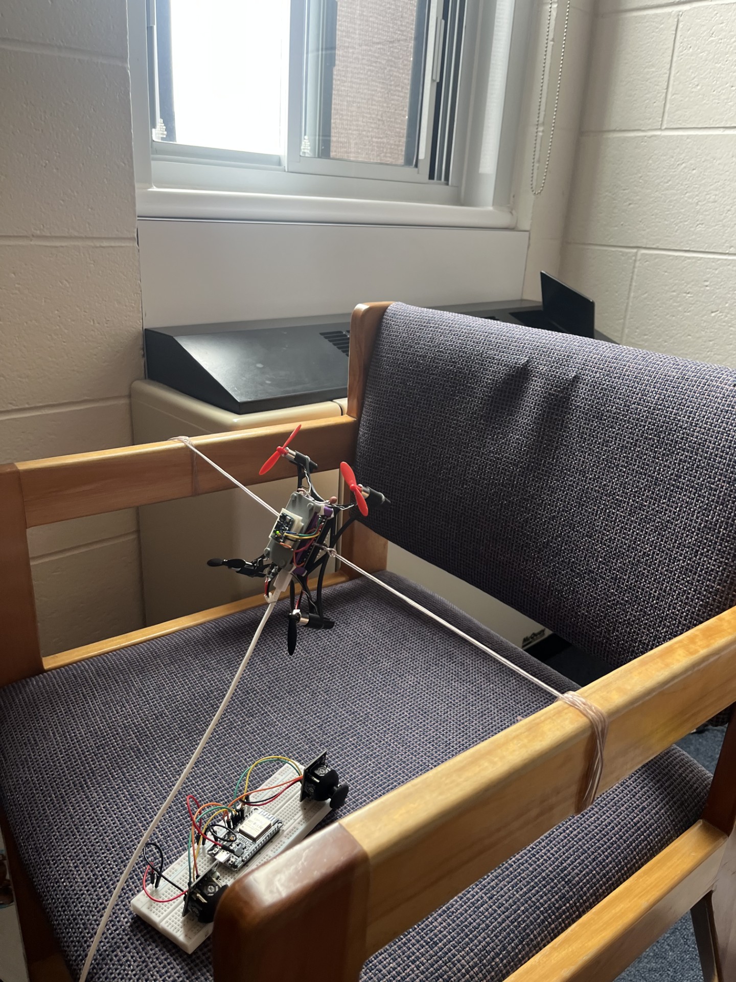
The firmware included compile-time test modes for equal thrust and one motor at a time; my notes separately document an earlier equal-duty check. I then progressed through individual motor troubleshooting, a multi-direction tether rig, and short free-flight attempts.
That progression makes the final lift meaningful without describing it as stable hover. It also exposed a design lesson: symmetric frame geometry was not the same as balanced mass and motor torque. The montage shows the brief airborne attempt along with close-up test footage.
05 / Tethered test
Inspect the restrained motor test
This separate close-up clip shows the assembled aircraft running its motors while restrained and responding to the handheld transmitter. It provides a clearer view of the hardware and motor outputs than the short flight footage.
Tools & technologies
- ESP32
- C/C++
- ESP-NOW
- I2C
- Madgwick
- PID
- PWM
- Autodesk Inventor